
Generic ModBus Adapter
Introduction
The Generic Modbus Adapter enables integration of Modbus-capable devices into the system. It acts as a flexible interface, allowing you to connect a wide range of sensors, controllers, and equipment that communicate via the Modbus protocol.
Adding the Generic Modbus Adapter in Device Management
To add the Generic Modbus Adapter, follow these steps:
Navigate to Device Management in the main menu.
Select New Device from Catalog.
Choose Generic Adapter from the list of available device types.
Select Modbus Adapter.
(See Figure 1 for reference.)
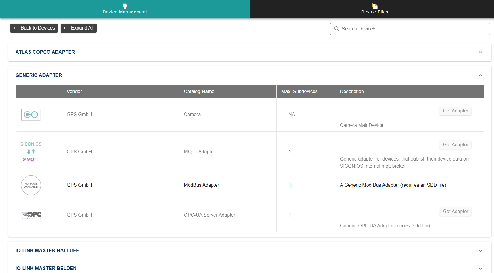
Figure 1
Configuring the Modbus Adapter
Once the adapter has been added:
Enter the IP Address of the Modbus server you wish to connect to in the input field provided.
(See Figure 2 for reference.)
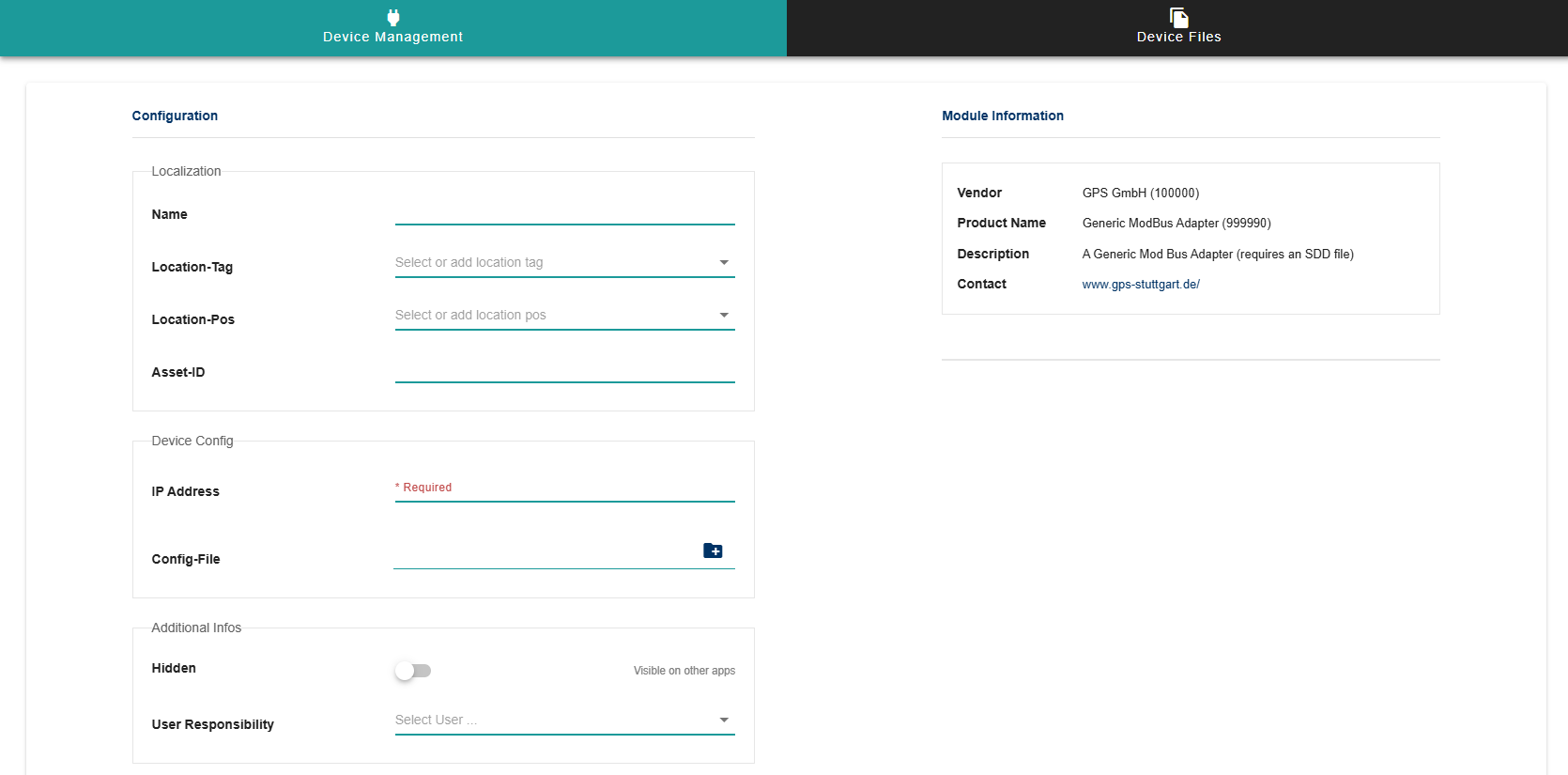
Figure 2
Device Description File (SDD)
The Device Description File (SDD) defines what needs to read / written from / to the Modbus Server.
The SDD file is mandatory for the Generic Modbus Adapter.
Relevant SDD files for supported devices can be downloaded via Sicon Finder.
Defining an SDD for a Generic Modbus Adapter
Defining an SDD for a Generic Modbus Adapter
The Device Description File (SDD) for the Generic Modbus Adapter contains standard fields, along with additional configuration for Modbus-specific communication.
RequestObject
Each field that needs to be read from or written to the Modbus device requires a RequestObject entry in the SDD.
"RequestObject": "{\"modbusAddress\":31,\"modbusLength\":2,\"modbusFC\":\"03\"}" Any field that needs to be read from the sub-device requires an additional key of RequestObject in the SDD. The RequestObject is broken down into 3 parts:
modbusAddress: The starting register or coil address on the Modbus device to read from or write to.modbusLength: The number of consecutive registers or coils to read/write starting at the given address.modbusFC: The Modbus Function Code (e.g.,03= Read Holding Registers) that defines the operation type.
The currently supported function codes include 1 - 6, 15 and 16.
Device Control RequestObject
The device control RequestObject(list) is included in config.DeviceControlDatawhere each index corresponds to the range defined in DeviceControl.
This structure allows the Generic Modbus Adapter to know exactly which registers to read or write for each sub-device, ensuring accurate communication with the Modbus server.
Adding a Siemens PAC3220 via Generic Modbus Adapter
The Siemens PAC3220 energy monitoring device can now be added via device management in the SICON.OS using the Modbus Generic Adapter.
Required Files
SDD File: The SDD for PAC3220 can be downloaded from: SDD - Siemens PAC3220
IP Address: After connecting the PAC3220 to the Sicon box, the device’s IP can be identified using the network scanner.
(See Figure 3 for reference.)
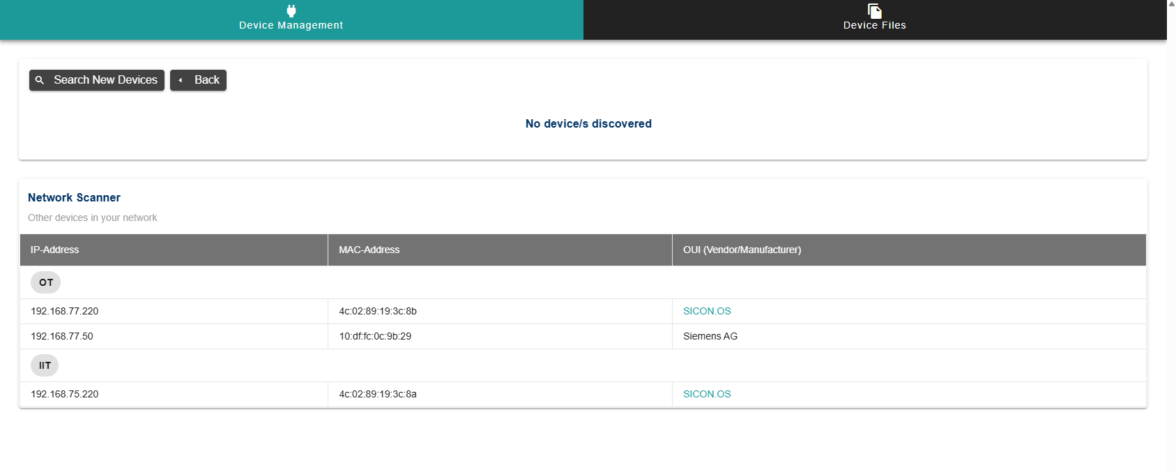
Figure 3
Adding and Configuring the Device
Follow the steps to add a Generic Modbus Adapter in Device Management.
Use the downloaded PAC3220 SDD file to configure the adapter.
Enter the IP Address of the PAC3220 as obtained from the network scanner.
Example Sub-Device Configuration
Once the adapter is added and the SDD file is loaded, the sub-device representation in the system will reflect the PAC3220 configuration.
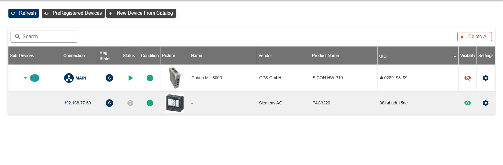
Figure 4
Identification
For device identification, the SDD file includes a snippet as shown below:
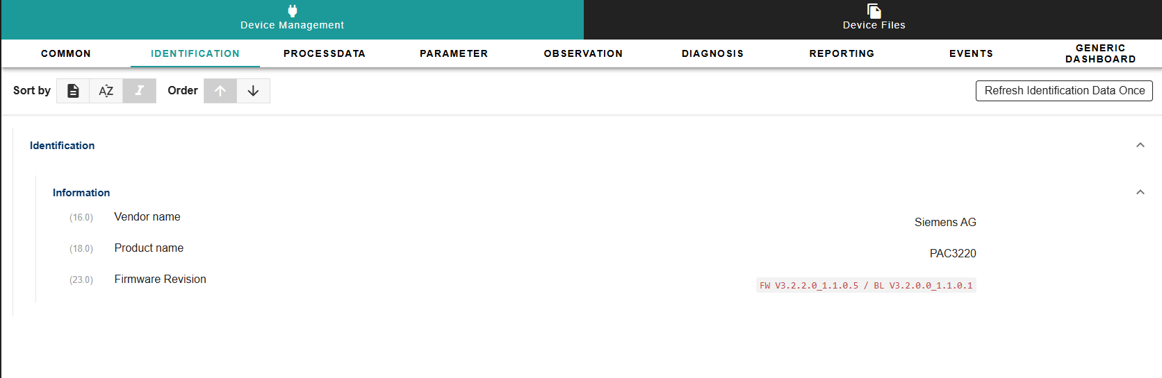
Figure 5
"Identification": {
        "Information": {
            "VendorName": {
                "Index": 16,
                "DataType": "StringT",
                "Access": "r",
                "Label": "Vendor name",
                "Value": "Siemens AG",
            },
            "ProductName": {
                "Index": 18,
                "DataType": "StringT",
                "Access": "r",
                "Label": "Product name",
                "Value": "PAC3220",
            },
            "FirmwareRevision": {
                "Index": 23,
                "DataType": "UIntegerT",
                "Access": "r",
                "Label": "Firmware Revision",
                "Value": "FW V3.2.2.0_1.1.0.5 / BL V3.2.0.0_1.1.0.1",
            }
        }
    }
Above is a snippet from the SDD file for Device Identification.
In this case,
RequestObjectis not defined because device identification for the Siemens PAC3220 requires Modbus function code 2B, which is currently not supported in SICON.Instead, the
Valuefield is used in the SDD to provide identification information.
Process Data
The process data tab contains the current total and per phase values of:
Reactive Power
Active Power
Apparent Power
Voltage
Current
Power Factor
Frequency
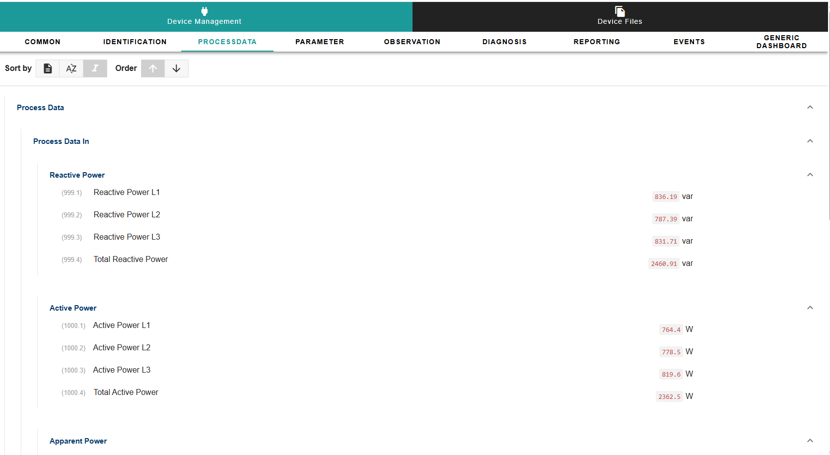
Figure 6
Below is an example of adding RequestObjectfor reading the values from the device. (Line 15 & 28)
    "CyclicData": {
        "ProcessDataIn": {
            "ReactivePower": {
                "ReactivePowerL1": {
                    "Index": 999,
                    "Label": "Reactive Power L1",
                    "DataType": "Float32T",
                    "Unit": "var",
                    "Subindex": 1,
                    "BitOffset": 736,
                    "BitLength": 32,
                    "Access": "r",
                    "Gradient": "1",
                    "Resolution": "Dec.2",
                    "RequestObject": "{\"modbusAddress\":31,\"modbusLength\":2,\"modbusFC\":\"03\"}"
                },
                "ReactivePowerL2": {
                    "Index": 999,
                    "Label": "Reactive Power L2",
                    "DataType": "Float32T",
                    "Unit": "var",
                    "Subindex": 2,
                    "BitOffset": 704,
                    "BitLength": 32,
                    "Access": "r",
                    "Gradient": "1",
                    "Resolution": "Dec.2",
                    "RequestObject": "{\"modbusAddress\":33,\"modbusLength\":2,\"modbusFC\":\"03\"}"
                },
Parameters
The parameter tab contains device control that allows several readings to be reset e.g. max values, min values, etc
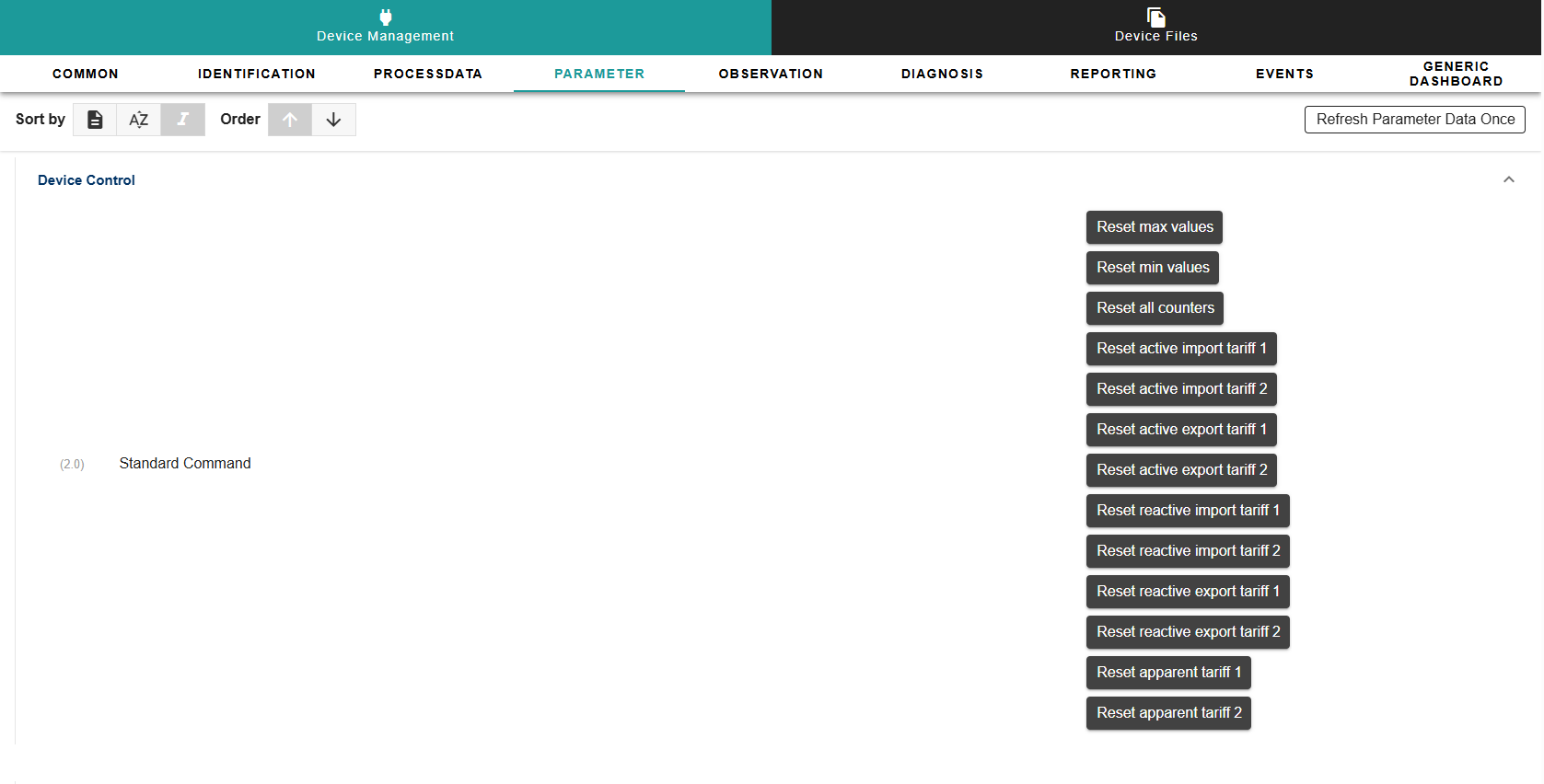
Figure 7
The corresponding SDD snippets is required to implement the above device controls.
    "DeviceControl": {
        "Commands": {
            "SystemCommand": {
                "Size": 8,
                "Remark": "",
                "ParameterDescriptor": "0=Reset max values,1=Reset min values,2=Reset all counters,3=Reset active import tariff 1,4=Reset active import tariff 2,5=Reset active export tariff 1,6=Reset active export tariff 2,7=Reset reactive import tariff 1,8=Reset reactive import tariff 2,9=Reset reactive export tariff 1,10=Reset reactive export tariff 2,11=Reset apparent tariff 1,12=Reset apparent tariff 2",
                "Range": "0,1,2,3,4,5,6,7,8,9,10,11,12"
            }
        }
}, "config": {
"DeviceControlData": {
"0": {
"RequestObject": "{\"modbusAddress\":60002,\"modbusLength\":1,\"modbusFC\":\"06\"}",
"Value": 0
},
"1": {
"RequestObject": "{\"modbusAddress\":60003,\"modbusLength\":1,\"modbusFC\":\"06\"}",
"Value": 0
},
"2": {
"RequestObject": "{\"modbusAddress\":60004,\"modbusLength\":1,\"modbusFC\":\"06\"}",
"Value": 0
},
"3": {
"RequestObject": "{\"modbusAddress\":60004,\"modbusLength\":1,\"modbusFC\":\"06\"}",
"Value": 1
},
"4": {
"RequestObject": "{\"modbusAddress\":60004,\"modbusLength\":1,\"modbusFC\":\"06\"}",
"Value": 2
},
"5": {
"RequestObject": "{\"modbusAddress\":60004,\"modbusLength\":1,\"modbusFC\":\"06\"}",
"Value": 3
},
"6": {
"RequestObject": "{\"modbusAddress\":60004,\"modbusLength\":1,\"modbusFC\":\"06\"}",
"Value": 4
},
"7": {
"RequestObject": "{\"modbusAddress\":60004,\"modbusLength\":1,\"modbusFC\":\"06\"}",
"Value": 5
},
"8": {
"RequestObject": "{\"modbusAddress\":60004,\"modbusLength\":1,\"modbusFC\":\"06\"}",
"Value": 6
},
"9": {
"RequestObject": "{\"modbusAddress\":60004,\"modbusLength\":1,\"modbusFC\":\"06\"}",
"Value": 7
},
"10": {
"RequestObject": "{\"modbusAddress\":60004,\"modbusLength\":1,\"modbusFC\":\"06\"}",
"Value": 8
},
"11": {
"RequestObject": "{\"modbusAddress\":60004,\"modbusLength\":1,\"modbusFC\":\"06\"}",
"Value": 9
},
"12": {
"RequestObject": "{\"modbusAddress\":60004,\"modbusLength\":1,\"modbusFC\":\"06\"}",
"Value": 10
}
}
}The RequestObjectincase of device controls is defined in the config object in SDD. Valuefield holds what is to be passed/written to the device.
Observation Data
The observation tab contains total energy (active & reactive) values since start of device.
The average, minimum and maximum values are for the demand period specified.
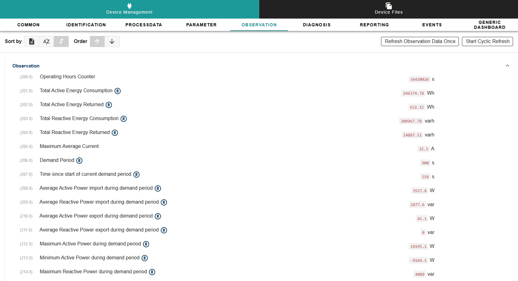
Figure 8
An example of the corresponding SDD snippet is as follows for observation data. RequestObjectdefined on lines 7 & 16 define the address and function code used to read the values from the device.
    "Observation": {
        "OperatingHours": {
            "Index": 200,
            "DataType": "UIntegerT",
            "Access": "r",
            "Label": "Operating Hours Counter",
            "RequestObject": "{\"modbusAddress\":213,\"modbusLength\":2,\"modbusFC\":\"04\"}",
            "Unit": "s"
        },
        "TotalActiveEnergy": {
            "Index": 201,
            "Label": "Total Active Energy Consumption",
            "DataType": "Float32T",
            "Unit": "Wh",
            "Access": "r",
            "RequestObject": "{\"modbusAddress\":2801,\"modbusLength\":2,\"modbusFC\":\"03\"}",
            "Gradient": "1",
            "Resolution": "Dec.2"
        },
Reporting Data
In order to create reporting data, we utilise the SDD again and define the indices that need to be included in the reporting data.
An example of how to define the indices can be seen below:
    "Reporting": {
        "Indices": [
            {
                "201.0": "PM"
            },
            {
                "202.0": "PM"
            },
            {
                "203.0": "PM"
            },
            {
                "204.0": "PM"
            },
            {
                "206.0": "PM"
            },
It should be noticed that these indices are the ones that we defined while writing observationin the SDD.
(CyclicData indices should not be used for reporting).