
PickBeam - Operating Instruction
Note:
Please retain a copy of the printed version of this document for future reference. Technical changes may be made without prior notice. No liability is accepted for printing or other errors.
Published by
© GPS GmbH,
This document is protected by copyright. GPS GmbH reserves all rights therein. Reproduction of the content, even in part, is only permitted within the limits of the statutory provisions of copyright law. Any changes or abridgements to the document are strictly prohibited without the express written consent of GPS GmbH.
GPS GmbH · Nobelstr. 15 · 70569 Stuttgart, Germany · T: +49 711 6870 31 30
info@gps-stuttgart.de
Important information
1.1 The technical documentation is part of the product.
Keep the technical documentation close to the product so that it is easily accessible, and follow the instructions carefully.
Pass on the technical documentation to the subsequent users.
Warning:
Failure to observe the instructions in the operating manual may result in life-threatening injuries!
GPS GmbH accepts no liability for damage or malfunctions resulting from failure to observe these instructions.
If you have any questions about the technical documentation, please contact us: info@gps-stuttgart.de
1.2 Note on using this operating manual
This operating manual contains important information and instructions for the various operating phases of the product:
Transport, storage, commissioning and decommissioning.
Safe operation, necessary maintenance and troubleshooting.
The manual describes the product as supplied by GPS at the time of delivery. The images are for reference only and may vary depending on the product configuration.
Basic safety instructions
1. Intended use
The PickBeam is an industrial-grade control and sensor unit designed for monitoring and control in industrial environments. It combines flexible LED line management, precise detection of environmental parameters and secure IIoT connectivity in a compact and robust device.
2. Improper use
GPS GmbH accepts no liability for direct or indirect losses or damage resulting from the use of the product. This disclaimer applies in particular to any use of the product that deviates from its intended purpose or is not described in this documentation.
3. Staff qualifications
⚠️ Unqualified personnel may overlook hazards. This can lead to increased risks!
Electrical work and installations may only be carried out by qualified electricians.
Assembly and installation may only be carried out by qualified specialists.
This operating manual is intended for specialists with experience in handling the product and its installation.
4. Signal words in this document
Warning notices indicate potential hazards when handling the product. The signal word indicates the degree of danger.
Signal word | Significance |
| High-risk hazard that could result in death or serious injury. |
⚠️ Caution | Low risk, which may cause minor or moderate injuries. |
| Important information about using the device. |
:note: Note | Additional information or tips to help you use the device. |
✅Tip | Important tips for using the device. |
5. Environmental and operating conditions
The PickBeam may only be operated under the following conditions:
Temperature range from -20 °C to +60 °C.
Maximum relative humidity 90%, non-condensing.
![]() Danger: The product must not be operated in potentially explosive atmospheres. This could result in an explosion.
Danger: The product must not be operated in potentially explosive atmospheres. This could result in an explosion.
If in doubt, please consult GPS GmbH before operation.
6. Technical condition:
Operating the product in a defective condition may compromise safety and functionality.
The product must be operated in technically perfect condition, i.e. in its original condition.
The maintenance schedule must be adhered to.
If there are any changes in operating behaviour, the device must be checked immediately for faults and these must be rectified.
If the fault cannot be rectified immediately, switch off the device and mark it as defective.
Any unauthorised modifications and alterations are prohibited.
Do not make any changes to the software.
7. Responsibilities of the operator with regard to country-specific regulations:
Comply with country-specific regulations on accident prevention, safety inspections and environmental protection.
Product safety information
Please read the following information carefully. The manufacturer accepts no liability for improper use of the product.
Read these instructions thoroughly before operating the device.
Installation and maintenance must only be carried out by qualified personnel.
Avoid exposing the device to water or extreme temperatures to prevent damage.
The housing must not be opened or modified.
Ensure that all cable and mounting connections are secure and stable to prevent malfunctions.
Keep the product out of the reach of children.
The operating voltage must not exceed the maximum values specified in this operating manual.
Observe the maximum values of the potential-free contacts if you use them.
Introduction
This user manual describes the installation, configuration and use of the PickBeam IIoT device. The device is designed for industrial applications and integrates sensor technology, lighting and communication functions. It enables the control of LED lines (coloured RGB LED light strips) and integration into existing networks via Ethernet or WLAN.
Scope of delivery
Contains | |
Device | PickBeam |
Power supply | 5 V / 15 A adapter with cable (optional) |
Assembly materials | Screws, DIN rail adapters |
Quick guide | 🖨️ Print version |
Optional accessories | |
LED lines | |
Sensors for temperature, humidity and other measured variables | |
Button for manual operation | |
LED lines longer than 5 metres can be used with accessories. Please contact the manufacturer for more information. | |
Advantages of your PickBeam
Individual control of LEDs possible.
Variable brightness adjustable.
Various colours available.
Up to 10 m length per LED line with optional accessories available.
Integration of various sensors possible.
Can also be used in mobile scenarios via Wi-Fi.
Setting up your PickBeam
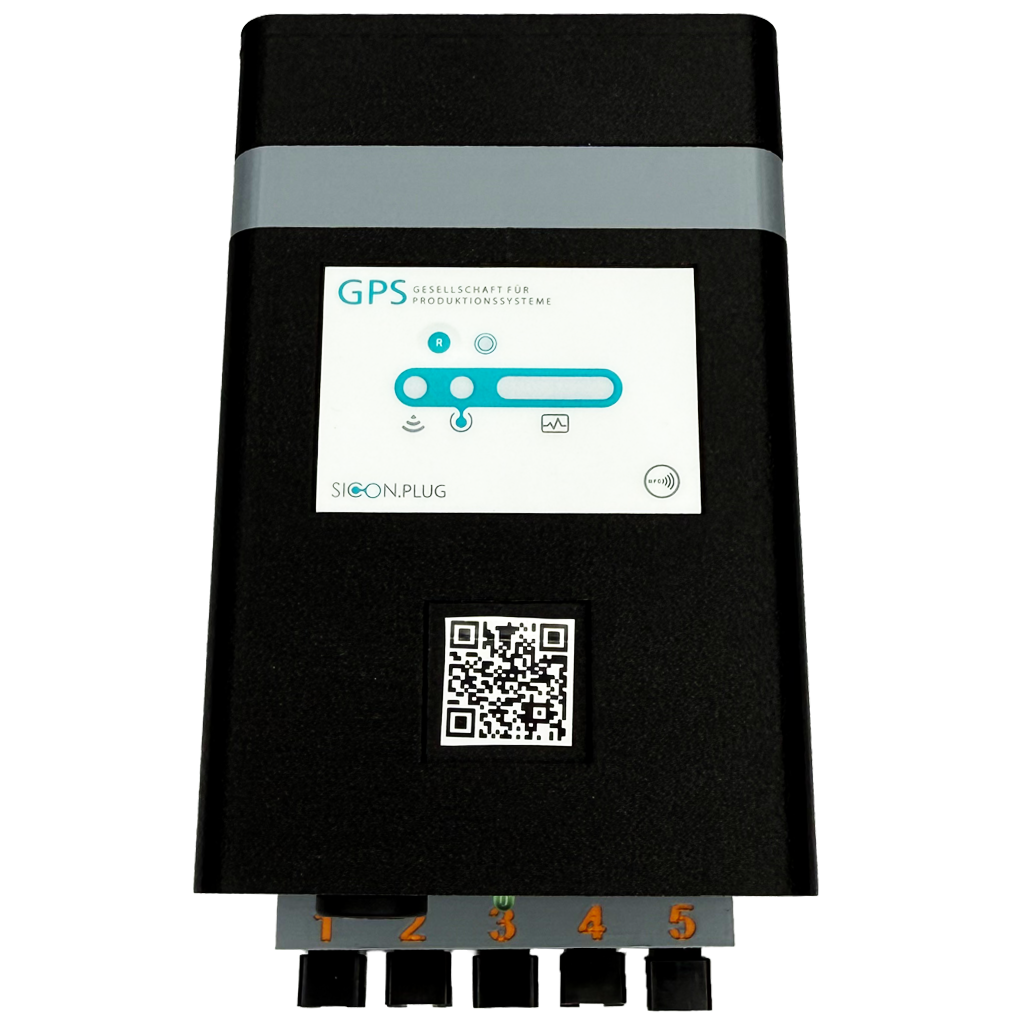
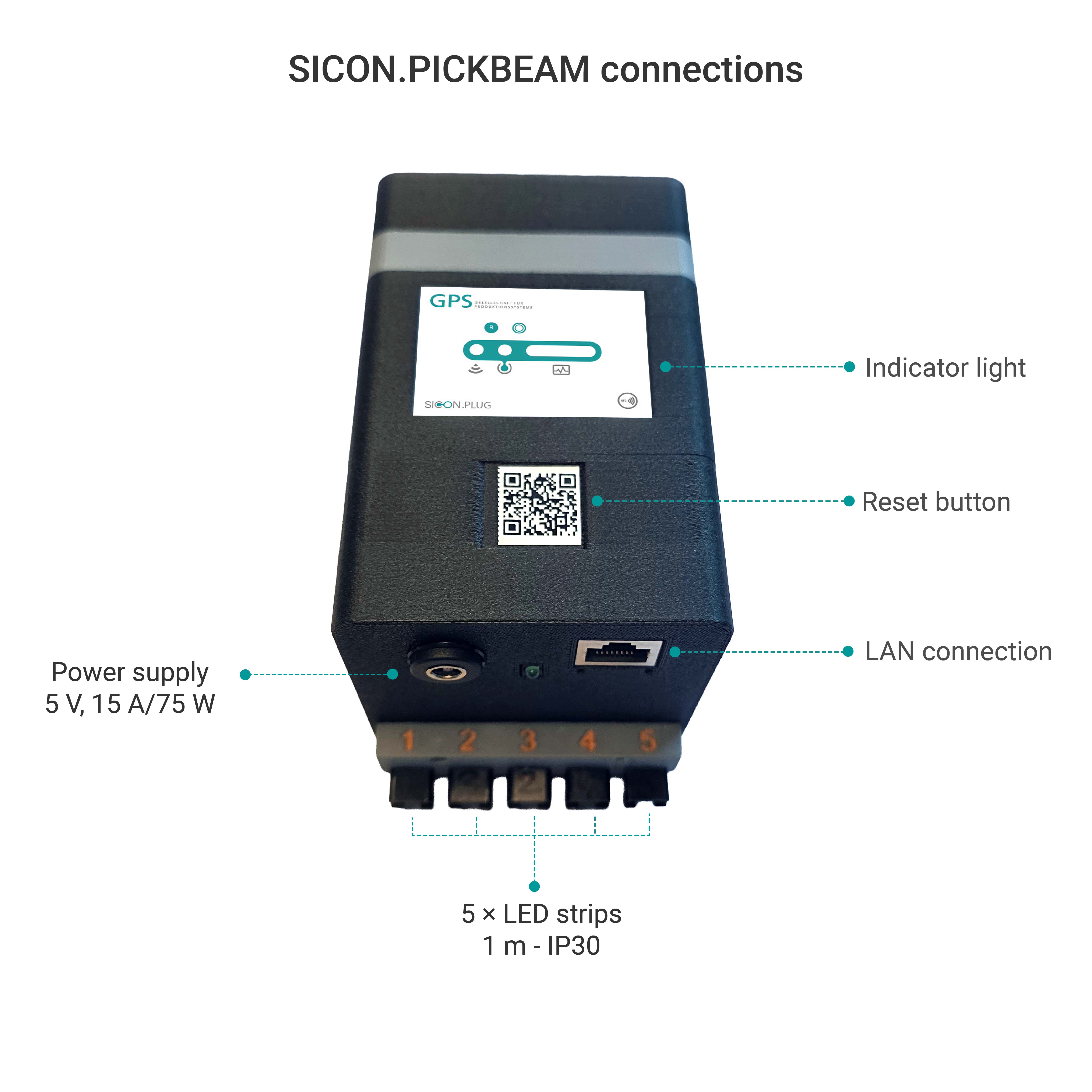
1.1 Controls on the front panel
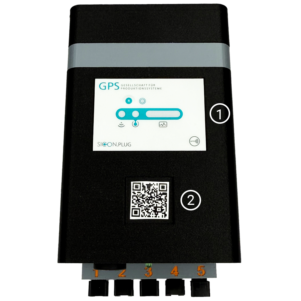
Indicator light:
The indicator light shows the status of the device.
Reset button:
Pressing the reset button resets the PickBeam to its factory settings.
Action | Duration | Function |
Press | 8s | Reset PickBeam to factory settings |
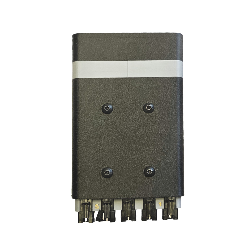
1.1.2 Back Side
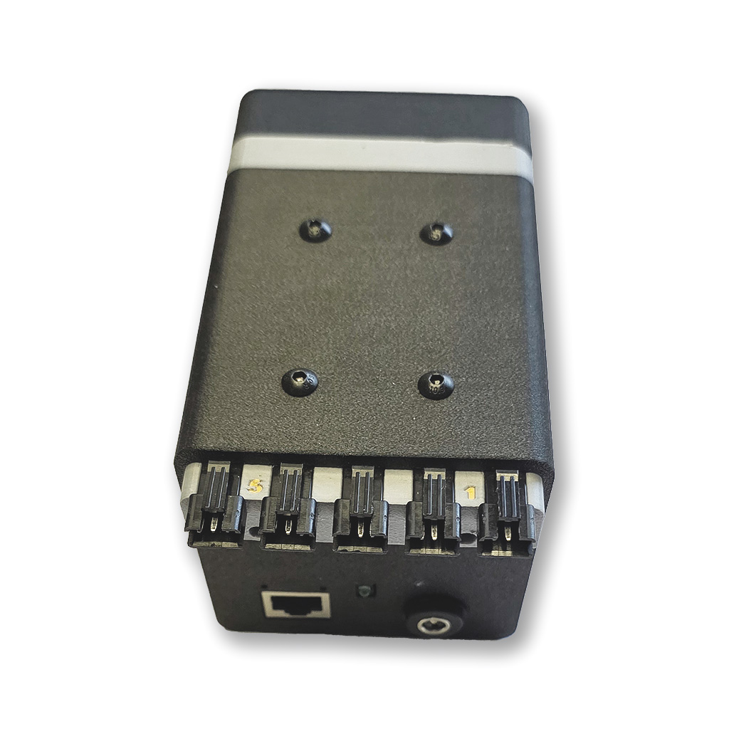
1.2 Connections on the Lower side
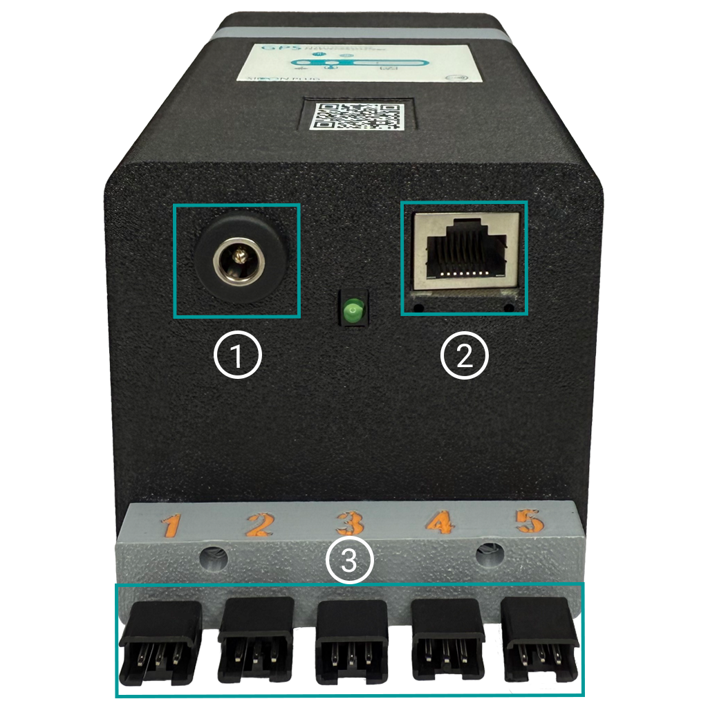
Power supply (5V): Connecting the power supply unit
LAN connection: Connection to the LAN network
5 LED connections: Connection sockets for the LED lines (can be equipped as required up to a length of 10 m each)
Installation
PickBeam installation in 5 steps:
Note
Please note the following points when choosing the installation location:
Do not install the PickBeam in a damp environment.
Protect the device from high mechanical stress.
Keep the PickBeam away from objects that generate excessive heat.
If possible, avoid areas with strong magnetic fields.
Step 1: Assemble the device
Check that the delivery is complete and inspect the device for visible damage.
For your safety, disconnect the device from the mains during installation work.
Always ensure that cables are routed safely and do not pose a trip hazard.
Install the device so that it is clearly visible to the operator.
The minimum distance to heat sources (e.g. heaters) is 30 cm.
Mount the device on a DIN rail, on the wall or on a pipe with a diameter of 28 mm. Use the supplied mounting materials to ensure secure fastening.
Step 2: Connect peripherals
Connect up to 5 LED strips to the corresponding outputs on the PickBeam.
The order of the outputs can be arbitrary.
Observe the maximum length of the LED strips and the number of LEDs per strip to avoid overloading.
The device with the supplied power supply supports up to 720 LEDs per line.
For longer LED lines up to 10 m, the extended power supply must be used (can be ordered separately).
Step 3: Establishing the network connection
Use the designated Ethernet port (see Fig. 1) to connect to the SICON.OS middleware.
Alternatively, you can also connect via Wi-Fi.
Have your SSID and Wi-Fi password ready to enable access to the middleware.
Step 4: Connect the power supply unit
Connect the device to the supplied power supply unit or to a high-quality, stable 5 V DC power source (max. 15 A).
Use a high-quality power supply unit to avoid voltage fluctuations.
If you want to extend LED lines from 5 m to 10 m, connect the optional extended power supply unit.
Step 5: Software setup
PickBeam can be set up with iOS, Android or Windows devices. Select one of the following three setup methods that suits your hardware (iPhone, Android smartphone or Windows PC/laptop).
Download the SICON.Toolbox app for your platform from here and install it:
Einrichtung - SICON.Toolbox App
5.1. iOS setup with iPhone:
Open the App Store on your iPhone or iPad.
Search for the PickBeam app and install it.
Launch the app and connect to the PickBeam device via Bluetooth.
Follow the instructions on the screen to complete the configuration, including setting up the network and LED lines.
5.2. Android setup with Android smartphone or tablet:
Open the Google Play Store on your Android device.
Search for the PickBeam app and install it.
Launch the app and connect via Bluetooth.
Follow the on-screen instructions to configure the device, including network connection and LED lines.
5.3. Windows setup with PC/laptop (EXE installer)
Download the Windows installer.
Run the file and follow the on-screen instructions to complete the setup.
This method is ideal for company laptops running Windows and offers the same configuration options as the mobile apps.
✅ After setting up on any platform: Ensure that your PickBeam device is connected to the SICON.OS middleware to obtain full functionality.
Configuration
Initial configuration
Connect the 5V power supply to the designated output (see Fig. 1). The device will then boot automatically and confirm that the LED lines are connected correctly with the following light sequence:
The first 8 LEDs of each strip light up for 10 seconds in the following colour sequence (the corresponding hexadecimal colour definition for each colour is shown in brackets; without configuration, the LEDs light up CONTINUOUSLY; the white boxes symbolise white LEDs, the grey boxes are unlit LEDs):LED line 1: Red (#FF0000)
LED line 2: Green (#00FF00)
LED line 3: Blue (#0000FF)
LED line 4: Yellow (#FFFF00)
LED line 5: Magenta (#FF00FF)
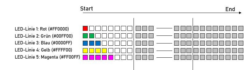
Abbildung 5
This check can be repeated at any time by pressing the reset button (see Figure 4) for 2–8 seconds until the LED strips are correctly assigned.
After the initial boot process, the device status light flashes blue (see Figure 1), indicating that the PickBeam device is in setup mode.
Configure the device for your network and system using the ToolboxApp (available for free download from the respective stores for your Android or iOS device). Go to the section "Configuration with the ToolboxApp".
Once the lengths have been configured correctly (see point 6), the lighting sequence changes: the first 8 LEDs and the last 8 LEDs of each LED line light up for 10 seconds in the respective line colour (see Figure 5) (the white boxes symbolise white LEDs, the grey boxes are unlit LEDs). Carefully check the length and number of LEDs against your configuration – incorrect configuration can lead to malfunctions later on.
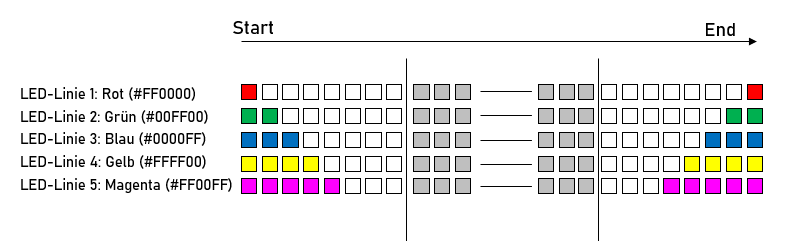
Abbildung 5
As long as the correct number of LEDs per LED line is not configured, only the first 8 LEDs will be activated.
Configuration with the ToolboxApp
Set up via the SICON.ToolBox App.
Download the ToolboxApp free of charge onto your mobile device, e.g. smartphone (from the App Store for iOS devices and Google Play Store for Android devices).
Connect to the PickBeam in setup mode.
Enter your network details (Ethernet or Wi-Fi SSID and password).
Complete the configuration to integrate the device into your system.
Check firmware
Open the SICON.OS interface > go to the Device Management area.
More information below Device Settings
Check for the latest firmware version.
If necessary, download the latest firmware and install it on your device to ensure optimal performance and security.
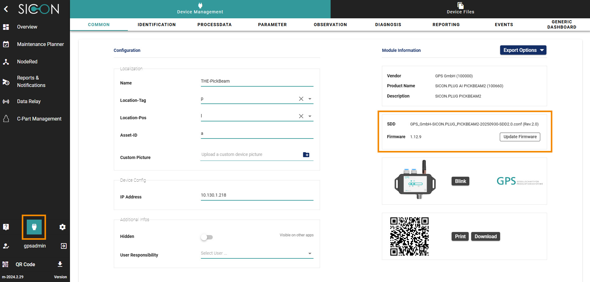
Figure 6: Device Management interface screen
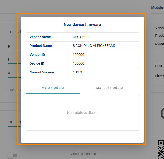
Figure 7: Device Management Firmware Interface Screen
Calibration of the sensors
Calibrate the integrated or external sensors according to the instructions in SICON.OS DeviceManager.
Ensure that the sensors are correctly connected before starting calibration.
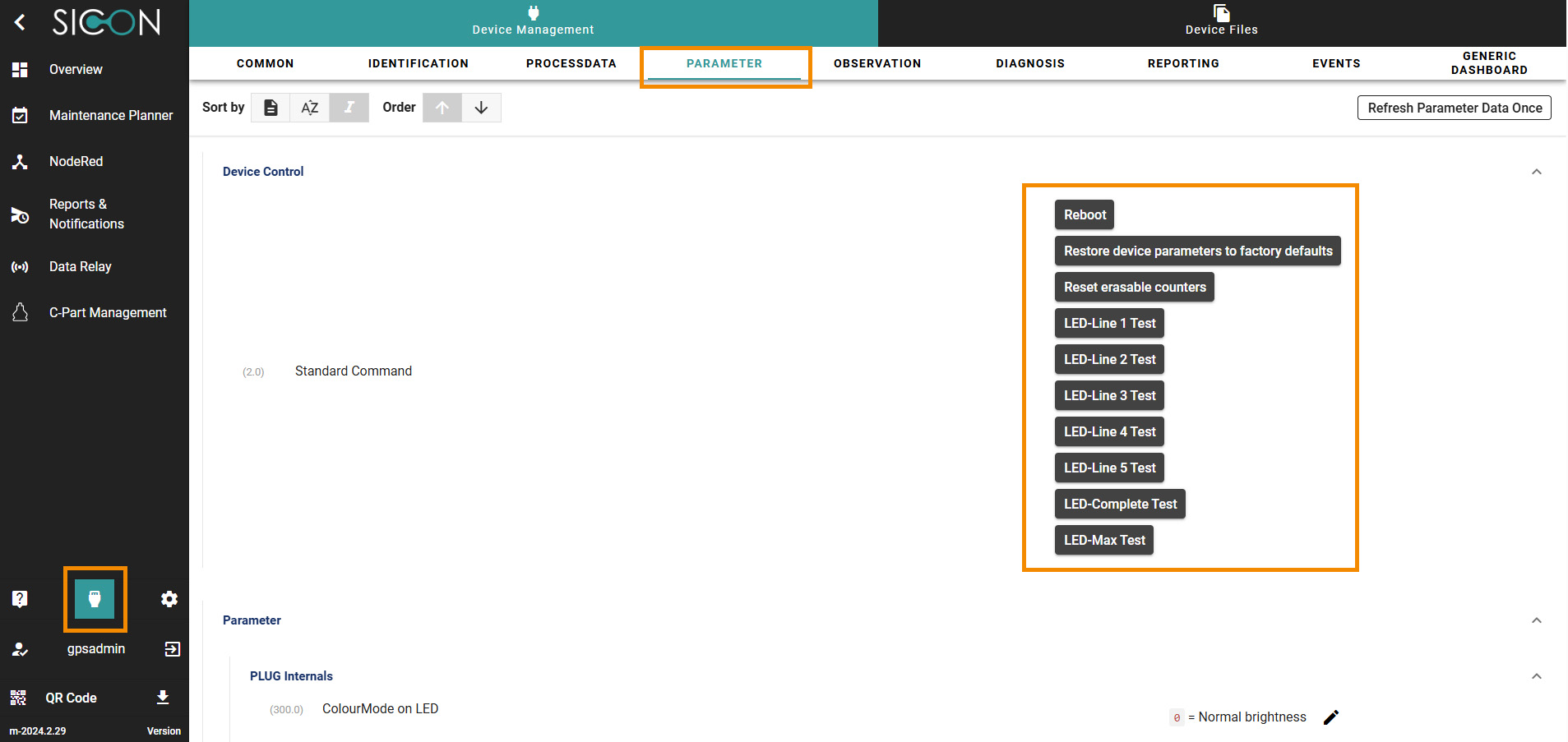
Figure 8: Device Management Parameters interface screen
LED control
Enter the correct length of each light strip in the configuration of the SICON.OS Device Manager.
Use the following buttons in SICON.OS DeviceManager to check:
LED Complete Test: Plays the start sequence for all light strips.
LED Max Test: Illuminates all light strips from the centre to the end.
LED Stripe X Test: Plays the start sequence for the respective light strip X and then illuminates all LEDs from the centre.
Adjusting the control for the LEDs
Select the desired programming interface for controlling the light strips:
MQTT-API
REST-API
Optional: Enable push notifications (webhooks) that send the current IP address to a defined remote station each time the system boots.
For a detailed configuration of the APIs, consult the API documentation and the examples in the use cases.
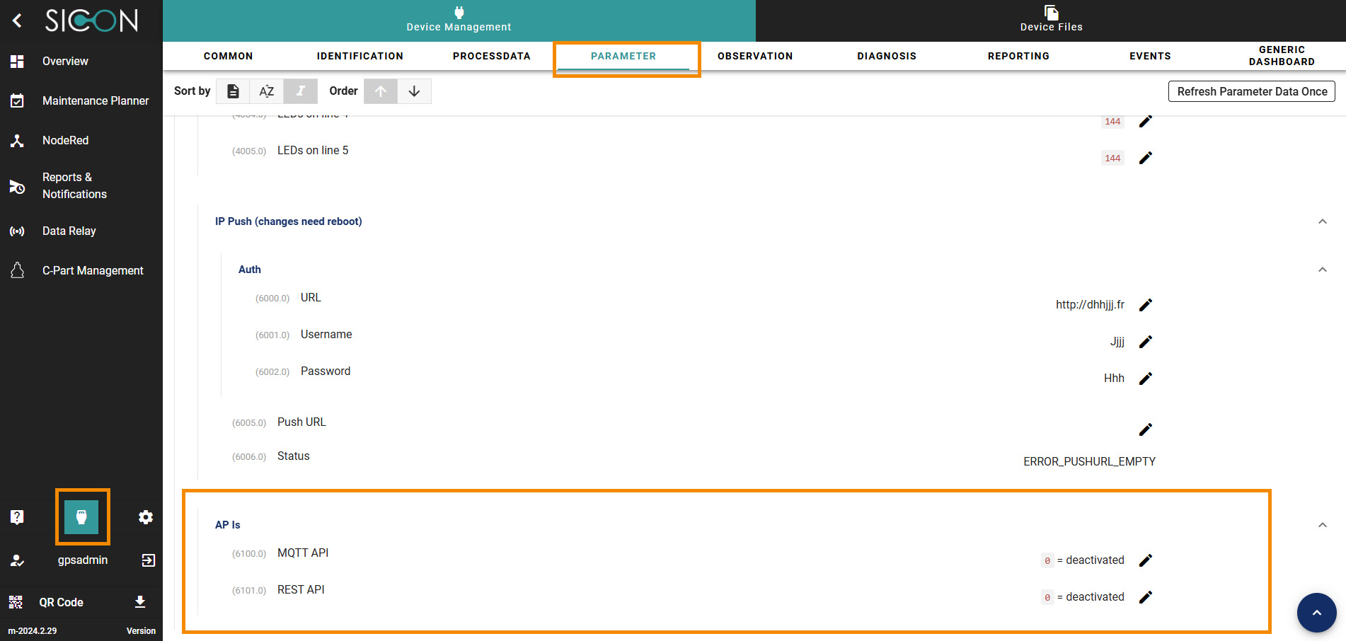
Figure 9: Interface mask Device Management Parameter API
Operation
Normal Operation:
The device monitors environmental data and sends it to the SICON.OS middleware via MQTT. The environmental data is stored at 1-minute intervals and can be exported or output as a report in a CSV file.
The light strips can be used for signalling applications (e.g. red for alarm).
Web-Interface :
Access via browser: http://[Middleware].
Dashboards for sensor values, LED control and logs.
Maintenance and safety
Regularly inspect the housing and cables for damage.
Clean only with a dry, lint-free cloth – do not use liquids or solvents.
Firmware updates may only be carried out via the SICON.OS platform.
Repairs may only be carried out by the supplier.
CE conformity and disposal of old equipment
The manufacturer GPS Stuttgart GmbH confirms that the PickBeam product described in this operating manual complies with the following relevant EC directives:
The following harmonised standards were applied:
EN 61000-4-2: 2009 Electromagnetic compatibility - Discharge of static electricity
EN 61000-4-3: 2006 Electromagnetic compatibility - High-frequency electromagnetic fields
Housing | Polycarbonate |
Seal | TPE |
Screws | Galvanised steel |
Executive committee | Mixed material Plastic Metal |
Disposal:
PickBeam contains electronic components and must not be disposed of with household waste.
Disposal must be carried out in accordance with the applicable legal regulations (e.g. ElektroG, WEEE).
Return old devices to authorised collection points or via the supplier.
Packaging materials can be recycled.
Contact and Support
Manufacturer:
GPS Gesellschaft für Produktionssysteme GmbHNobelstr. 15, 70569 Stuttgart
support@gps-gmbh.deVersion of the Operating instructions: 1.0 (September 2025)