Operating instruction for SICON.PLUG AI PVS
Note
The product information is originally written in German. Please retain a copy of this document for future reference. Subject to technical modifications without prior notice. No liability is assumed for printing or any other errors.
Published by
© GPS GmbH, 02/24
This document is protected by copyright. GPS GmbH retains the rights established therein. Reproduction of the contents, whether in full or in part, is only permissible within the boundaries of the legal provisions of copyright law. Any alterations to or abbreviations of the document are strictly prohibited without explicit written consent from GPS GmbH.
GPS GmbH · Nobelstr. 15 · 70569 Stuttgart, Germany · T: +49 711 6870 31 30
info@gps-stuttgart.de
Important Information
1.1 The technical documentation is a part of the product.
Keep the technical documentation near the product for easy access and follow the instructions carefully.
Share the technical documentation with subsequent users.
Attention:
Not adhering to the instructions mentioned in the operating manual may result in life-threatening injuries!
GPS bears no liability for damages or malfunctions resulting from non-compliance with these instructions.
If you have any queries about the technical documentation, please contact us at: info@gps-stuttgart.de
1.2 Note on Using these Operating Instructions
This operating manual includes important details and guidance for various stages of the product's operation:
Transport, storage, start of operations and decommissioning.
Safe operation, necessary maintenance, and troubleshooting.
The manual describes the product as provided by Schmalz at the time of delivery. Images are for reference only and may vary based on specific product configurations.
Fundamental Safety Instructions
1. Intended Use
The SICON.PLUG ANALYTICS PVS is a system for retrofitting existing pneumatic systems. With the integrated overpressure and vacuum sensors, pressure profiles can be analysed and compared.
The SICON.PLUG is set up via an APP. To do this, the user must provide information about their pneumatic system and the associated data hub, which can be local or in a cloud.
The system sets itself up automatically during the first 30 minutes and continues to learn during production.
It monitors the health of the system, alerts the user to a possible failure and calculates the right time for maintenance in advance.
2. Non-Intended Use
GPS GmbH bears no liability for direct or indirect losses or damages occurs from the use of the product. This disclaimer applies specifically to any use of the product that deviates from its intended purpose or is not described in this documentation.
3. Personnel Qualifications
Unqualified individuals may overlook hazards, which may lead to increased risks!
Electrical work and installations may only be handled by qualified electricians.
Assembly and adjustment work may only be performed by qualified individuals.
These operating instructions are intended for skilled technicians who are expertise in product handling and installation.
4. Warnings in This Document
Warnings alert about potential hazards during product handling. The signal word signifies the level of danger.
Signal word | Meaning |
DANGER | High-risk hazard that could cause death or serious injury if not avoided. |
WARNING | Moderate-risk hazard that could cause death or serious injury if not avoided. |
CAUTION | Low-risk hazard that could cause minor or moderate injury if not avoided. |
NOTE | Danger that may result in property damage. |
5. Environmental and Operating Conditions
The SICON.PLUG ANALYTICS PVS must be operated only under the following conditions:
Temperature range from 0 °C to + 50 °C.
Maximum relative humidity 90%, non-condensing.
Avoid list: The product must not be operated under the following conditions:
Operating the product in an explosive environment may lead to an explosion.
In case of doubt, please consult GPS before operation.
6. Technical Condition:
Operating the product while in a defective state may impaired the safety and functionality.
The product must be operated when in perfect technical condition, i.e., its original state
Maintenance plan must be followed.
If there are changes in the operating behaviour, immediately examine the device for faults and address them accordingly.
If the fault cannot be immediately addressed, switch off the device and label it as defective.
Any alterations or modifications which are unauthorized, are prohibited.
Do not make any modifications to the software.
7. Operator Responsibilities Regarding Country-Specific Regulations:
Adhere to country-specific regulations concerning accident prevention, safety testing, and environmental protection.
Product safety note
Please read the following information carefully. The manufacturer accepts no liability due to improper use of the product.
Keep the product out of the reach of children.
Please avoid cleaning the product with excessive use of water.
Please protect the open ports of the product from water, dust and dirt entrance by appropriate mounting or dust caps.
Protect the vacuum connections of the product from over pressure.
The operating voltage must not exceed the maximum values specified in these operating instructions.
Observe the maximum values of the potential-free contacts, if you use them.
Introduction
Congratulations, with the purchase of the SICON.PLUG ANALYTICS PVS, nothing stands in the way of your vacuum system being connected to the IOT. With the integrated vacuum sensors, pressure profiles can be analyzed and compared.
The SICON.PLUG is set up via an APP. To do this, the user must provide information about his vacuum system and the associated data hub, which can be local or in a cloud.
A transparent process, detailed analysis and predictive maintenance are just some of the benefits that make this product so innovative.
Within minutes, your SICON.PLUG ANALYTICS PVS is up and running and ready to provide you with real added value.
Advantages of your SICON.PLUG ANALYTICS PVS
Connection
No additional power supply required as the SICON.PLUG ANALYTICS PVS can be supplied directly with 24V industrial standard.
Network connection via 10 MBIT/s Ethernet or WLAN 2.4 GHZ with antenna according to IEEE802.11b/g/n possible.
High-speed transmission of measured data through modern scalable protocols.
integrated sensors
1 x pressure sensors with measuring up to 8bar
1 x vacuum sensors with measuring range down to -1000mbar / max. Overpressure 2 bar.
Easy discrete communication with a PLC or instant control of alarms and signalling devices through two dry contacts.
Industry 4.0 Ready
Relaxed secure global access to your data by transferring it to the cloud.
Intelligent user management ensures that each department sees the data that is important to them.
Simple commissioning via an app.
Easy configuration of parameters via an internet browser.
Analytics
Direct evaluation of your measured data and display via status LEDs using an innovative colour concept.
Predictive maintenance through sophisticated algorithms.
Messages and notes provide information on where there is still potential for improvement in your vacuum process.
The revolutionary replay function freezes your process. This allows errors and optimization attempts on the process to be analysed and tested in detail.
The built-in collision detection generates an error message as soon as, for example, an industrial truck collides with your vacuum system or a rough use has damaged it. This allows you to detect defective or critical machine conditions before they occur.
Structure of your SICON.PLUG ANALYTICS PVS
1.1 Front panel controls
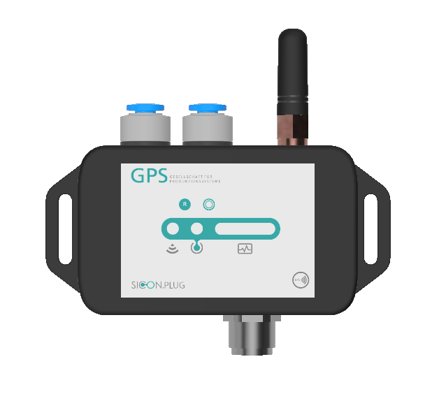
Power LED indicates whether 24V operating voltage is present at the SICON.PLUG ANALYTICS PVS. If this is the case, the LED lights up green.
Reset button this allows simple settings to be made directly on the device.
Status bar with one glance always immediately in view of the status of the machine and the SICON.PLUG ANALYTICS PVS.
NFC interface is not supported in the current version.
1.2 Controls on the upper side
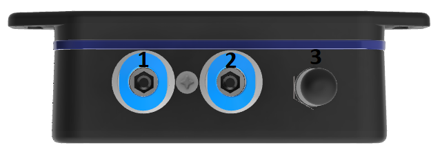
Vacuum input before the filter this connection is connected to the system between the vacuum generator and the vacuum filter. The labelling of the connection can also be found on the product label on the back of the plug.
Vacuum input after the filter this connection is connected to the system between the vacuum filter and the gripper. The labelling of the connection can also be found on the product label on the back of the plug.
WLAN antenna for wireless connection to the company network.
1.3 Controls on the bottom side

5-pin M12x1 plug connection for the supply of the operating voltage and the contact pins of the potential-free contacts.
RJ45 Ethernet socket for connecting the SICON.PLUG ANALYTICS PVS to the company network.
1.4 Status bar
The status bar on the front of the SICON.PLUG ANALYTICS PVS provides information about the current connections. In addition, the current machine status is visualized directly on the device.

LED | Action | Color | Cleartext |
1 | shines | Blue | Connection via WLAN |
1 | shines | Green | Connection via WLAN |
2 | shines | Green | Connection to IOT platform |
2 | blink | Red | No connection to the IOT platform |
3 | shines | Green | Machine status L0 |
3 | shines | Yellow | Machine status L1 |
3 | shines | Orange | Machine status L2 |
3 | shines | Red | Machine status L3 |
3 | blink | Red | Vacuum sensors are not calibrated |
3 | blink | Yellow | No filter reference value stored in the device |
All | shines | Yellow | The push button of the SICON.PLUG ANALYTICS PVS is pressed |
All | blink | Yellow | SICON.PLUG ANALYTICS PVS is reset to the factory settings |
All | shines | Green | Teaching of the reference vacuum value was successful |
All | shines | Red | Teaching of the reference vacuum value was not successful |
All | blink | Blue | SICON.PLUG ANALYTICS PVS is ready for registration |
All | blink | White | The device's flashing option was selected for identification |
1.5 Reset Button

The button can be used to reset the SICON.PLUG ANALYTICS PVS to its factory settings. The button can be locked via the software so that you do not have to worry about unintentional operation.
Attention! If you lock the button and no longer have access to the device via the software, resetting the device is no longer possible!
Action | Duration | Impact |
Push | 8s | SICON.PLUG ANALYTICS PVS is reset to the factory settings |
Lock | - | Locks the Fast Lane button so that it no longer functions. |
1.6 NFC interface
The NFC interface is not available in the current version.
1.7 Gyroscope and accelerometer
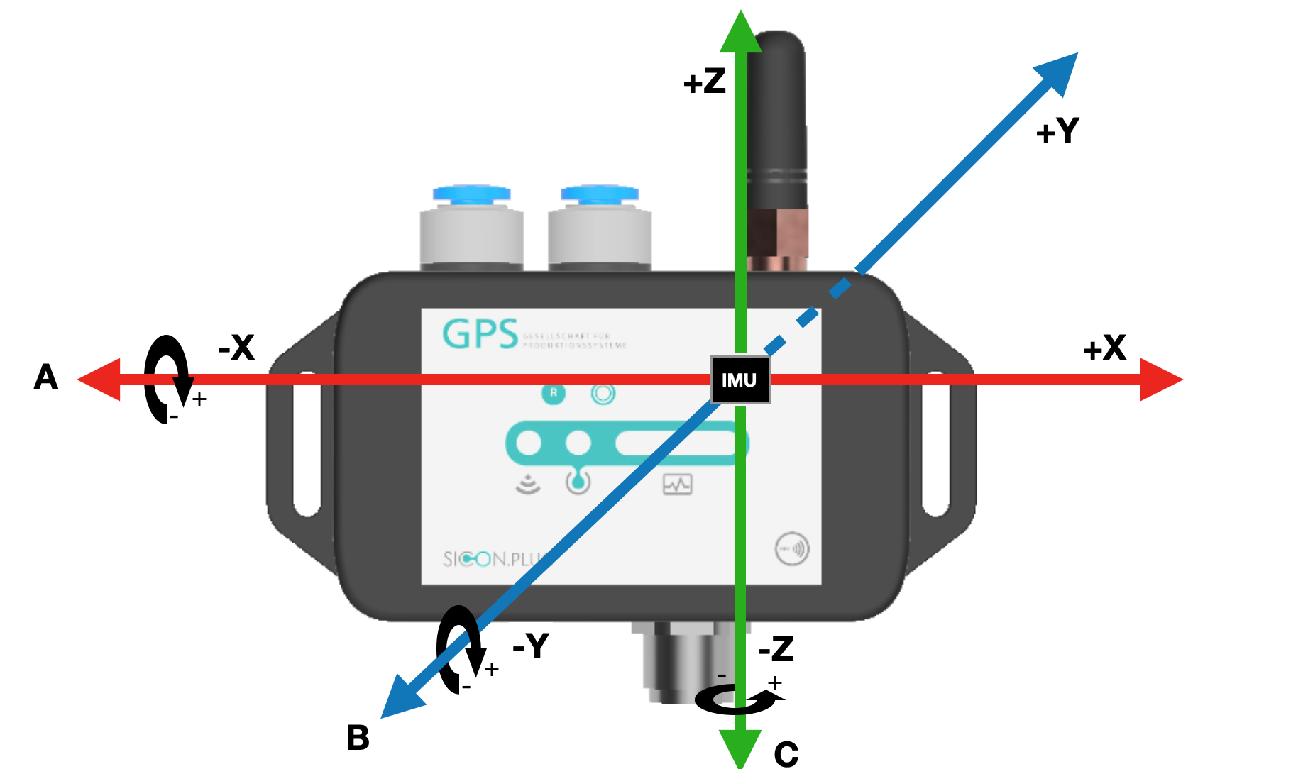
The SICON.PLUG ANALYTICS PVS has a built-in gyroscope and accelerometer. These can be used to measure and display crashes or vibrations that stress the system. The alignment of the sensors is shown in the image below.
Commissioning
Please follow the instructions for commissioning the device listed here exactly. Damaged devices due to improper commissioning or an unsuitable installation location will not be reimbursed. GPS Stuttgart GmbH accepts no liability for any damage to property or personal injury resulting from improper use of the device.
1.8 IT security and port sharing
In order for the plug to communicate with its data broker, it needs the shares listed below within its network. Please ask your IT department to assign these port shares to you. Operation without these shares is not possible. If you have any questions or doubts, please contact a member of GPS Stuttgart GmbH.
Port | Protocol | Direction |
OnCloud mode (plug sends data to the cloud) | ||
80 | TCP(HTTP) | Outgoing |
1883 | TCP(MQTT) | Outgoing |
OnSide mode (plug sends data to hardware within the network) | ||
80 | TCP(HTTP) | Bidirectional |
1883 | TCP(MQTT) | Outgoing |
1.9 Mounting location
In principle, the SICON.PLUG ANALYTICS PVS can be installed anywhere in your production or logistics environment. It is recommended to mount the SICON.PLUG ANALYTICS PVS in such a way that impacts against the rubber buffers of the system can be detected. Please ensure that the crane system is not damaged or its load-bearing capacity impaired during installation. When mounted in the immediate vicinity, vibration from the pump can be recorded. The maximum recordable vibration here is 25Hz. However, light impacts against the system can no longer be reliably detected by the motor vibrations.
Please observe the following notes when selecting your installation location:
Do not install the SICON.PLUG ANALYTICS PVS in wet environments.
Protect the device from high mechanical stress.
Keep the SICON.PLUG ANALYTICS PVS away from objects that generate a lot of heat.
Make sure that the mounting location does not have any pronounced magnetic fields, if possible.
1.10 Mounting
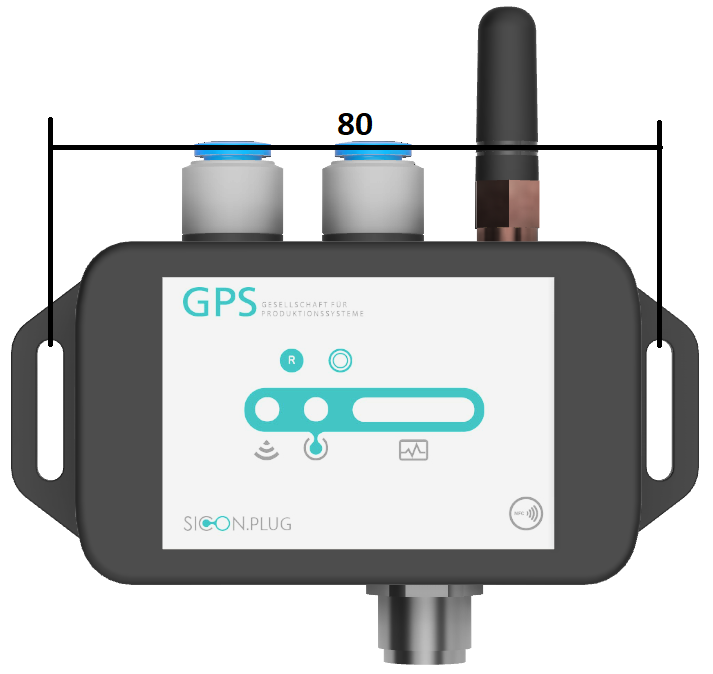
For the recommended mounting on the support of the vacuum system, you need two M3 cylinder head screws with hexagon socket and matching washers. First drill two D=2.5mm core holes with a borehole spacing of 80mm at the desired mounting location. Now cut an M3 thread into the two holes. You can then use the two M3 screws to screw the SICON.PLUG ANALYTICS PVS to the support via the slotted holes. The orientation of the SICON.PLUG ANALYTICS PVS is freely selectable, although the variant shown above is recommended.
1.11 Hosing
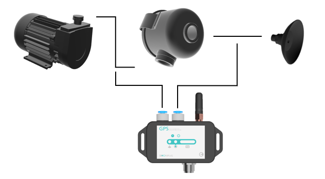
For the pneumatic installation, you will need approved pneumatic hoses with an outer diameter of 6 mm and pneumatic fittings as required to connect your existing vacuum system to the SICON.PLUG ANALYTICS PVS .
First switch off your vacuum system and make sure that the system is pressure-free. Then connect the left pneumatic connection of the SICON.PLUG ANALYTICS PVS to the vacuum system between the vacuum generator and the vacuum filter. Then connect the right connection to the vacuum system between the vacuum filter and the actuator.
This work should only be carried out by a specialist with sufficient knowledge of pneumatics.
1.12 Electrical connection
Work with electrical current should always be carried out by skilled personnel with the necessary training. Please get help if you do not have such training.
The SICON.PLUG ANALYTICS PVS is supplied with 24 V operating voltage. Please refer to the table below for the corresponding pins.
The two potential-free contacts are based on semiconductor technology, so no mechanical wear stands in the way of an application with many switching cycles. The respective signal branch is switched against the shared pin 5. This can be connected with a voltage up to 30 V or to ground.
The maximum current must not exceed 750 mA!
Voltage type | Min. | Typ. | Max. |
Operating voltage | 19,2 V | 24 V | 28,8 V |
Switching voltage (DC) potential-free contacts | 0 V | 24 V | 30 V |
Contact number | Designation | Core color standard actuator cable |
1 | +24 V | Brown |
2 | Switch contact 1 | White |
3 | -0 V | Blue |
4 | Switch contact 2 | Black |
5 | according to connection | Grey or Green |
Important functions
1.13 Resetting SICON.PLUG ANALYTICS PVS to factory settings
There are two ways to reset the SICON.PLUG ANALYTICS PVS to its factory settings.
Press and hold the Reset button. This will cause the status bar to light up yellow. After approx. 8 seconds, it will start to flash. After a total of 12 seconds, the status bar goes out. When the button is released, the SICON.PLUG ANALYTICS PVS is now reset to its factory settings. If the reset is successful, the status bar pulses blue after a short wait.
The SICON.PLUG ANALYTICS PVS can also be reset very conveniently with the SICON.OS software. To do this, go to the Assets program. Then go to the Settings of the device to be reset and to the PARAMETERS tab. Here you will find the button restore device parameters to factory defaults. Click on it. The status bar on the SICON.PLUG now disappears completely. After a few seconds, it pulses blue. The SICON.PLUG ANALYTICS PVS is now reset to its factory defaults.
1.14 Calibration of the vacuum sensors
The vacuum sensors of the SICON.PLUG ANALYTICS PVS must be calibrated during initial start-up. This status is indicated by a red flashing LED 3. Calibration is performed via the SICON.OS software.
Make sure that no pressure, neither over pressure nor under pressure, is applied to the sensors during the calibration process.
Calibration can be carried out at any time via the software when no pressure is applied. To do this, go to the Assets program. Then go to the Settings of the device to be calibrated and click on the PARAMETERS tab. Click on the Calibrate Vacuum Sensors button. A successful calibration is visualized by the green illumination of the entire status bar. If calibration fails, the status bar lights up red.
1.15 Storing a filter reference value in SICON.PLUG ANALYTICS PVS
For analyses of the filter and the entire vacuum system, it is necessary to store a reference vacuum value in the SICON.PLUG ANALYTICS PVS . A missing reference value is indicated by the yellow flashing of LED 3.
Switch on your vacuum generator and ensure that your system can freely draw in air. Now you can store a reference value.
Attention! This function is always available, please make sure that you do not enter incorrect values.
Via the SICON.OS software you can make the referencing via the Assets program. Click on the settings of the selected device. Now you can store a value by clicking on the button Teach in a reference vacuum value which you can find in PARAMETER.
1.16 Lock reset button
If you want to lock the reset button against unauthorized access or accidental operation, you can do this via the SICON.OS software. To do this, go to the Settings of the device to be locked in the Assets program and to the PARAMETERS tab. Select Lock push button in the dropdown list of index 12 and save the settings by clicking on the save icon.
1.17 Machine condition level
A deviation of your desired process data can be set via the machine condition level. The normal values of your process should be in the middle of the graphic shown below (green area). If your actual value drifts into another range, an event is generated and the LED3 of the PLUG changes color accordingly. The switching thresholds to another level can be set via the SICON.OS software. To do this, go to the PARAMETERS tab in the Assets program. Here you will find all switching thresholds that can be changed in the PLUG.

Tips and help
1.18 Technical data
Technical data | |
|---|---|
Manufacturer | GPS GmbH Stuttgart |
Operating voltage | 24V DC +/- 20% |
Rated current | 100mA |
Dimensions | 90mm x 43mm x 26mm with tabs for M3 screws |
Weight | 300g |
LAN interface | 10Mbit/s |
WLAN interface | IEEE 802.11 b/g/n 2,4GHz |
1.19 CE conformity and disposal of old equipment
The manufacturer GPS Stuttgart GmbH confirms that the SICON.PLUG ANALYTICS PVS product described in these operating instructions complies with the following relevant EC directives:
The following harmonized standards have been applied:
EN 61000-4-2: 2009 Electromagnetic compatibility - Static electricity discharge
EN 61000-4-3: 2006 Electromagnetic compatibility - High frequency electromagnetic fields
Please dispose of the product properly after replacement or decommissioning in accordance with the country-specific guidelines and legal obligations for waste prevention.
Housing | Polycarbonate |
Seal | TPE |
Screws | Steel galvanized |
Board | Mixed material plastic metal |
Next steps
Setting Up via the SICON.ToolBox App.
How to's 👉 Quick start installation video